1. Block-Structured Meshes
This tutorial shows how to agglomerate block-structured grids with linear elements to get a high-order mesh consisting of fully curved hexahedral elements. The parameter file can be found in
tutorials/3-01-agglomeration_NACA/parameter.ini
1.1. Restrictions on the block-structured meshes
HOPR poses the following restrictions on the provided block-structured meshes:
One block face must be exclusively associated to one boundary condition. Block faces with multiple BCs or a combination of boundary and internal element faces on a single block face are likely to produce wrong mesh topology! The user is responsible for splitting blocks in such cases. Otherwise, HOPR will be unable to perform the mesh connect step!
When providing a block-structured mesh for agglomeration, only one unique factor is permitted in the
I,J,Kdimension of all blocks!
Each boundary conditions present in the provided mesh must be matched in the parameter file by its name and an associated boundary type:
        BoundaryName = wall_1
        BoundaryType = (/4,0,0,0/)
        BoundaryName = wall_2
        BoundaryType = (/4,0,0,0/)
Boundary names can match multiple BCs by specifying only the common part of the boundary name string. In the example above, BoundaryName=wall would match all boundary conditions.
1.2. Initial Meshes
Agglomeration of block-structured meshes provides a simple and robust curving technique for the generation of three-dimensional high-order meshes. In HOPR, mesh agglomeration is controlled by the MeshIsAlreadyCurved parameter. The application of mesh agglomeration is demonstrated on two meshes of a NACA-profile provided as CGNS files. Here, mesh 1 is suitable for inviscid simulations without boundary layer refinement and mesh 2 features boundary layer refinement.
Mesh1: NACA0012_icem_32elems.cgns

Fig. 1.1 Cross-section of initial mesh 1 |

Fig. 1.2 Zoom on the leading edge of mesh 1 |
Mesh2: NACA0012_icem_viscous_32elems.cgns
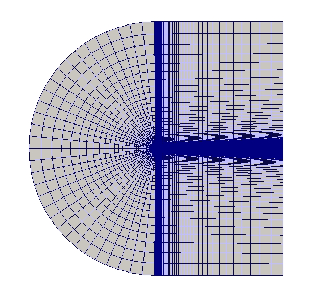
Fig. 1.3 Cross-section of initial mesh 2 |

Fig. 1.4 Zoom on the leading edge of mesh 2 |
All of the following figures were created with mesh 1.
Agglomeration Curving Technique
When using agglomeration, the important parameters areMeshIsAlreadyCurved = T
useCurved = T
BoundaryOrder = 5
which lead to a coarsening in all three dimensions of the structured mesh, using the internal points as interpolation points for the curved mapping. The number of elements in each direction of the structured block must be a multiple number of BoundaryOrder-1! This situation is illustrated on an exemplary mesh in Fig. 1.5. For BoundaryOrder=2, the initial linear mesh retained without agglomeration.

Fig. 1.5 Block-structuring with the parameter BoundaryOrder=2/3/5, (BoundaryOrder-1)^3 elements are grouped together.
In addtion, the parameter nSkip can be set to coarsen the initial mesh.
1.3. Description of Parameters
The following table describes all parameters associated with agglomeration. A description of all parameters is given in List of Parameters.
Parameters |
Setting |
Description |
|---|---|---|
|
|
Enables the agglomeration |
|
|
Coarsing of block-structured meshes |
|
|
Only if the mesh is extruded in z-direction, a different nSkip can be given in z-direction. |

Fig. 1.6 Front view of the leading edge with the initial mesh configuration. All elements and edges are linear. |

Fig. 1.7 Front view of the leading edge of the mesh ( |

Fig. 1.8 High-order curved mesh generated through agglomeration. |
Coarsening
Mesh coarsening is controlled by two parameters: nSkip applies to all structured directions equally, and nSkipZ can be used for z-extruded meshes.

Fig. 1.9 Initial mesh ( |

Fig. 1.10 Coarsened mesh ( |

Fig. 1.11 High-order curved mesh generated through agglomeration. |

Fig. 1.12 High-order curved mesh generated through agglomeration. |
The figure on the left side shows the initial mesh. The parameter nSkip=1 uses every point of the initial mesh. The mesh in the middle-left shows the mesh if nSkip is set to 2. That means that one node in each direction of the respective coordinate system is skipped and that the size of the new element reaches to the next node. The skipped nodes will no longer be used for mesh generation, including curving. The parameter nSkipZ has the same function as nSkip but only applies towards the z-direction. By providing the nSkipZ parameter, the corresponding entry in nSkip is ignored.
The following figures illustrate possible combinations of the nSkip and nSkipZ parameters, each applied to the identical initial mesh. Keep in mind that reading in a block-structured mesh only works if the value for the parameter(s) nSkip (and nSkipZ) is a common divisor of the number of all mesh elements for each axis.

Fig. 1.13 Mesh 1 with following parameter settings: |

Fig. 1.14 Mesh 1 with following parameter settings: |
Fig. 1.15 Mesh 1 with following parameter settings: |

Fig. 1.16 Mesh 1 with following parameter settings: |
Correction for z-Extruded Meshes
Extruded meshes often suffer from issues with limited coordinate precision, preventing HOPR from finding corresponding surface elements on the upper/lower boundary. HOPR included a built-in correction routine for such cases. This function is not restricted to block-structured meshes, but can be applied to all meshes which are extruded along the z-direction. Enabling this setting requires five more parameters to be set.
Parameters |
Setting |
Description |
|---|---|---|
|
|
All elements are aligned exactly along z-direction to suppress grid generator errors |
|
|
The number of elements in z-direction (after agglomeration!) |
|
|
Set minimum z-coordinate |
|
|
Set length of domain in z-direction |
|
|
Boundary conditions ( |